Reviewing parts for LDraw
The LDraw family of programs are awesome tools for the serious Lego hobbyist. However, since they're free, it's up to the adult community - that's you and me! - to continually modeling the new parts the Lego Group supply us with.
However in order to get high quality parts that isn't too big, we have the Parts Tracker or PT where new parts are reviewed, commented on, and corrected before they're released in the official part updates from LDraw.org.
We always need more part authors and reviewers to contribute, so here's a tutorial on how you can help making a difference by reviewing parts. Long experience in modeling parts is not necessary - you'll gain incredible insight in authoring by reviewing (and vice versa). Doing both makes you an expert of both in no time. Getting reviewing rights is really easy, you just ask the admins of the Parts Tracker for it.
Assuming you’ve already tried to author parts and have now been granted reviewing rights, what do you do now?
Basics
First of all relax! Reviewing is nothing different than the error checking you usually do before submitting a part; it’s all about getting enough eyes on the part to find all errors (2 independent reviewers and one admin are required), and suggesting ways to improve the part. The worst trouble you’ll experience is to get the author (or somebody else that is working on the part) to fix the errors you find.
You could consider refraining from casting hold votes (and certification votes) at first, to avoid making errors and upsetting people until you get more experience but remember that another reviewer has to approve the file before it get released, so you can’t screw up badly! If somebody else detects an error and upload a new version of the file, your vote get deleted. And even after that, the PT Administrators need to accept the part as good.
Deciding which kind of vote is the proper response, is mainly based on experience and precedence build up over time, among other things scattered in various discussions on Lugnet.cad. Even though it would be really nice, this information has not been assembled and codified anywhere, but you’ll find some of it on this page.
Choosing a part
After relaxing a bit, it’s time to choose a part to review. It is totally up to you what part you decide to work with, although it is generally frowned upon to review parts you have made or altered since it is assumed that you already have found all the errors you could before submitting it. It is also a good idea to have the part in real life since you can’t adequately review a virtual part without the real one as a reference – on the other hand, we don’t want rare parts getting stuck in the PT just because none (or too few) of the reviewers have them!
You can pick a part you need for one of your models, one that looks like something you’ve worked with before, or one you just feel is important. Other options include picking from the Parts Tracker List, picking a freshly submitted part from the Activity list, or picking a neglected one from the File Queue (you have to be logged in from the main LDraw page to use this link).
The key is to shift around a bit between the categories and pick parts that interest you, so you stay motivated. But remember: the ugly, difficult, and stuck parts also need to be reviewed, so be responsible for the PT and pick one up once in a while.
Testing the part, basics
So what are you supposed to look for when reviewing a part? Basically there's three classes of potential errors you should look out for when reviewing parts:
- Does it look like the real life counterpart?
- Does the file correspond to similar parts already modeled? And
- Does the file contain bad lines of code?
1) Does it look like the real life counterpart? Naturally we all want our computer-generated models to look reasonably close to the real life stuff as possible. Of course the author will often leave out insignificant details to speed up authoring and calculating (the more complex parts are, the fewer of them can your computer handle).
2) Does the file correspond to similar parts already modeled? The majority of official parts are modeled at a certain size, position, and orientation:
Size: If the part is slightly too small or big, it wont fit the others and will look odd.
 Position: When it comes to position the standard is to place the part so that the origo (center coordinate 0,0,0) is situated at the top surface of the part (ignoring eventual studs) at the middle of the part (or logical rotation point: for instance in the hinges of hingeparts or corners in semi-circular parts like macaroni pieces so that you can easily add-turn, add-turn until you have a complete circle). If the part isn't positioned correctly before it's official release, we'll end up with an annoying part that need to be adjusted by every LDraw-user, every time it's used from now on and to the end of the world!
Orientation: New parts should also generally be turned the same way as similar parts: Consider what would happen if the 2x2 45 degree slope was turned 90-degrees compared to the other 45-degree parts: When laying roofs, you're supposed to be able to slap on rows and rows of slopes quickly, but a single wrongly orientated part would totally destroy the flow... from now on, rest of the world, etc..
3) Does the file contain bad lines of code? Bad lines or coding is the class of error you'll encounter most frequently: This is where things gets really nit-picky: Basically the part can look fine at a glance, but bad coding can result in all sorts of problems ranging from ridiculously large or unhandy files to "punctuated" parts with faulty or missing sections of surfaces that'll result in holes or unwanted transparency.
Basically all these three classes boils down to: Does the virtual part look right and is it easy to use?
Use of various programs for reviewing purposes
In the following I'll try to give an account of how I personally use a selection of programs to test parts before writing a review to the parts author.
Remember other programs like LEOCad and LDView can do many of the same things as MLCad and L3Lab, so you may want to adapt the

MLCad:
Use the part: I primarily use MLCad to check if the part "look right" a very basic and surprisingly effective way to check it is by simply opening the program (with a new untitled .ldr document), and adding the part to the document from wherever you've saved it on your computer: simply right-click anywhere in the windows, select "Add > Part", and check "Custom Part" and click "Browse" to fetch the file from where ever you've saved it on the computer:
Try to combine it with similar parts: is it positioned and oriented the same way so that it's possible to make larger uniform sections fast, for instance roofs made with slopes, without parts "jumping up and down" - or compare printed parts quickly in search of a particular pattern?
Double checking dimensions:
 MLCad provides the coordinates of anything you point at with the mouse - written in the lower left corner of the screen, this makes it fast and easy to check the dimensions and position of the part. Remember to mouse over the point in more than one window, as you can only get two coordinates at any time (in this example we're looking at the part head on, along the z-axis, and since - so there's no "depth" coordinate for that direction).
Size: The first thing I do is to check the coordinates of everything in MLCad: This program has the nice function, that it writes the coordinates of everything you point at with the mouse in the lower left corner: That means that you can check if the dimensions fit what you'd expect based on the real life version of the part, and if the center of the top is located at exactly (0,0,0).
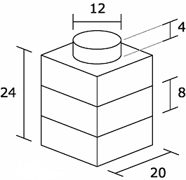 LDU = Lego Digital Units is the scale virtual parts in LDraw are created in. Read more on Brickwiki, where I've borrowed this illustration.
However, you need to be aware of two things:
First, most parts fit within a 20x20x8 LDU coordinate system (corresponding to an 1x1 plate), while the coordinates displayed will be affected by the grid coarseness you choose: using coarse grid will automatically round off coordinates to the closest 10 LDU, medium to the closest 5 LDU vertically- if you wish to spot errors of 1 LDU you have to use fine grid (and corresponding 8, 4 and 1 LDU horizontally).
Second, each of the three windows in the program display one side of the part: this means that you can only get two coordinates of each side: If you move the mouse over the window displaying the part from the top, you'll get the x and z coordinates, but not the y (height), using one of the side views will give you the height but leave out one of the vertical coordinates: You simply have to check via two windows each time.
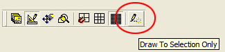 You find "Draw to selection only" next to the gridbuttons in the Mode-toolbar
After checking the position and size of the part, it's always a good idea to run the file through MLCad step by step with "Draw to selection only" turned on to get a general sense of what objects the file is made up of - how it's "build".
This is the place to visually search for basic errors where the part deviates from its real world counterpart, like polygons that don’t meet and edges that are missing or extend beyond the part. Furthermore this is usually the only way to find excess objects left over from the construction that ought to have been deleted when replaced with primitives or subfiles - and once in a while you'll actually come across weird stuff floating somewhere inside the part that can’t be seen from the outside.
 Spot the missing edges:
Another good function in MLCad is the "Wireframe" mode:
- You can turn on wireframe mode by right clicking the 3d window and selecting “Wireframe”. This enables you to spot missing edge lines very easily, because the other edges looks like weird “loose threads” sticking out into nothing - just turn and tilt the part to get a feeling of what edges goes where.
Note: Always remember that if you change something in MLCad it adds a couple of orientation lines to the file and changes the suffix of the file from .dat to .ldr:
0 ROTATION CENTER 0 0 0 1 "Custom"
0 ROTATION CONFIG 0 0
So try to avoid saving the file in MLCad, and if you have to, you need to delete the lines manually in LDDP (see below) and change the suffix back to .dat.

L3Lab:
The best use of L3Lab is to search for gaps where sections of the surfaces don’t meet up properly and locating BFC errors in the part.
BFC stands for “Back Face Culling” and is a way to make parts much more easy to handle for the computer because it only has to calculate how the outer surfaces look (as opposed to calculating both inner and outer surfaces). Since it’s pretty simple to BFC a part (especially if the author have done it right from the beginning), it is highly recommended that all parts entering the PT are made BFC compatible.
Check this tutorial for info on BFC’ing.
The main use of L3Lab is therefore to check for BFC errors, by selecting "Test > mytest6" in the top menu.
And btw, it’s often a really good idea to zoom in on the part by selecting "View > Zoom" and enter a good zoom level so the part fills the screen. Usually 500 tends to be a good level for parts.
 If the part turns up blue, it isn’t BFC compliant, and needs the tag 0 BFC CERTIFY CCW in the header – since both inside and outside of the surfaces are blue it’s really hard to check for gaps (another good reason to make parts BFC compliant).
If the part is a mixture of red and green, the part has the tag, but some of the surfaces are turned the wrong way so their back is showing – the red ones. Alternatively the problem can be “holes” in the part where sections don’t meet up properly.
Turn and tilt the part around in order to figure which one is the case.
When you’ve figured it out, you place a hold vote and comment where you tell the author to fix the problem (reversed surfaces or gaps) - if the part is BFC certified, but these errors aren't fixed, the red areas will simply become transparent on your renderings giving you a look right through to the interior of the part!
However in some cases, the author isn’t responding, or it’s your own part that is being reviewed, and that’s when you need LDDP.

LDDP:
Lego Digital Design Pad is the main tool for finding and fixing all the nit-picky problems usually can't be spotted visually, but will cause the computer to stumble.
Error check: The first thing you'll want to do with LDDP is to run an error check - this of course need to be configured to work: "Open Tools > Options" and click the "Configuration Values"-tab. It should look something like this:

Here you can change the thresholds of how nit-picky the check should be. It's usually best to keep to the suggested values, although some files will be considered ok with less accuracy, and high resolution primitives should have more.
 If the values are OK, you just click the check button or F10.
This may turn up a lot of different errors, you can see an extensive list here and a description of what to do.
Usually you'll just notify the author that there is errors and let him find them himself: he actually ought to have run the test before submitting the part - as well as after he's (hopefully) fixed the errors.
If you wish to be nice, you can always post the numbers of the lines with BFC-errors, but I personally think it's a waste of time: he need to run the check himself sooner or later anyways.
Fixing winding and non-coplanar errors via LDDP: As mentioned in the L3Lab-section, you sometimes have to fix files yourself. Here's a description on how to fix three of the most widespread problems with a really clever combination of LDDP and L3Lab:
At first LDDP will need to know where you've installed L3Lab: Select "Tools > Options" and click the "External Progs"-tab. In this window, and browse to the program's location (do the other ones as well now you're there):

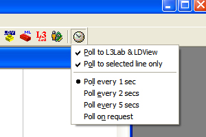 Then you need to set up the so called polling function, click the poll-button and make sure it looks like the picture on the right:
After this you can open a L3Lab-window by clicking the L3Lab-button, and you can run the file through line by line, while L3Lab will update and show the progress through the file once every second.
This is especially useful for fixing reversed quads and triangles as described in the L3Lab-section, because when you've turned "Test > mytest6" on, you can just browse through the file until you hit upon offending lines and then reverse them with the reverse winding button (see 3rd picture above), Ctrl-W, or F12 .
Sometimes you'll hit upon 3D primitives like cylinders or boxes that are turned the wrong way, in this case you should add a line saying
0 BFC Invertnext
Just before it. If it already has one, it's probably because the author has moved another primitive and forgotten the invertnext-tag. In this case you just delete the line to reverse the primitive.
Flat primitives like discs and rings should not be reversed with the invertnext-tag, but turned manually with MLCad (again: remember to remove the two rotation tags in the front of the file every time you change something in MLCad).
 Bow-tie quads:
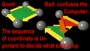
Besides flipped objects, the most common error you'll find will be bow-tie quads (L3P Check reports them as bad vertex sequences) and non-coplanar vertices. Both types have to do with wrong coordinates of the corners in quads, and will be explained shortly in the following:
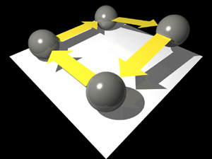
In a quad, the corner coordinates need to follow a certain sequence (clockwise or counter clockwise around the quad), and be level.
You get a bow-tie quad if two of the corner coordinates are swapped (like 1-2-4-3), because instead of neatly following the edge around the quad (1-2-3-4) it skips directly from 2-4 right over the centre, goes back to 3, and skip directly to 1 from there.
This means that you’d have to decide on which pair of coordinates to swap, and do it manually via LDDP, example:
4 16 1x 1y 1z 2x 2y 2z 4x 4y 4z 3x 3y 3z
should be changed into:
4 16 1x 1y 1z 2x 2y 2z 3x 3y 3z 4x 4y 4z
if it’s the last two coordinates that have been swapped: it could also be 1-2, 2-3 and 4-1.
When you've swapped two coordinates, run another check to see whether you’ve fixed the problem . REMEMBER - you may have fixed the bow tie problem, but unknowingly have flipped the quad backside out, so save and check it via L3Lab: If the quad turns up red, you need to go back and reverse it like explained at the beginning of this section.
 Non-coplanar:
The problem with non coplanar quads is that not all corners are level: Imagine a four legged stool where one is too short: It can rock back and forth because only three legs can touch the ground at any moment. The computer wont be able to figure out which three coordinates is the right position, if “the stool is right in forward or backward position” – all coordinates need to be level.
These errors can be particularly nasty to get rid of, because you have to figure out which corner is the wrong one and after that calculate how much it needs to be raised or lowered to fit the rest. And quads with this problem are almost always pretty odd shaped and sitting at some weird angle, which makes this problem very difficult to solve.
Besides bow-tie and non coplanar, the L3p check in LDDP also searches for a variety of other errors, read more about L3p check in this list.

POV-Ray (+ L3PAO):
One of the main reasons for working with Lego on your computer is that you’re able to make beautiful renderings via programs like POV-Ray, so the parts necessarily need to look good there as well.
One of the final checks is to do a couple of renderings of the part from different angles: Surfaces may look like they’re touching each other in the other programs but have glaring black seam in POV-ray because they don’t connect properly. The rendering is also an extra security against any holes you might have missed before: Both seams and holes will usually appear pitch black.
And while you’re at it: Make sure you render the pictures in quality 3 so you can check the little Lego logo on the studs: Often it’s turned at some wrong angle compared to the physical part turned in different direction, or simply mirrored (especially on older parts).
Technically it’s not a reason to cast a hold vote, but it looks stupid, and it must be considered ‘good practice’ to fix it, so ask the author to fix it – it’s really easy.
Note 1: Although you can use LDView for most of the rendering check instead of POV-Ray, LDView automatically unmirrors mirrored studlogos, so you can’t be sure to detect this errors with the studlogos here, and should at least make one good close POV-render of the top of the part with quality 3 to be sure.
Note 2: Note also that you’ll need to install L3 to convert the LDraw files to POV-Ray in the first place. L3 is an old dos program, but before you panic, there’s a nice little graphical windows program, L3PAO that lets you easily control the L3 program without coding in the dreaded prompt mode.
To sum things up:
1) Run the part through MLCad to get a general sense of the layout, looking for excess objects and missing objects like edgelines.
2) Check for BFC problems and gaps via L3Lab (mark them via MLCad and fix them via LDDP)
3) Check for Bow-ties, non coplanar and other stuff via L3p check in LDDP
4) Render the part via POV-Ray to see whether it looks good there as well.
If you have the physical part yourself, you should check with it often, and especially during step 1.
3 rules of efficient reviewing
Here are some good rules of thumb that will reduce friction and frustrations when working with the PT and thereby make the process a lot more efficient.
#1 Don’t touch!
It’s the author’s part and if you put your greasy hands on it you sacrifice your ability to certify it, because you then become co-author: so now instead of just needing the attention of two more reviewers to look at before it can be turned over to an admin, it now needs a third one to show up and take YOUR place casting that second certification vote you burned. This can easily be translated into at least 50% longer staying time in the PT.
Furthermore, remember that the author has spent a lot of time making the part and usually develops a feeling of ownership. Messing with their part can make them quite angry and/or cut them off from great learning experiences.
However, often you'll come across parts in the PT that has had a hold-vote (or important no-votes) for a very long time that indicate that the author has abandoned it: In this case somebody else has to step up and fix it.
The LDraw Steering Committee has decided on these policies regarding when it's ok to take over parts.
Just remember, that if another reviewer has already worked on the part, you should consider him the "new author" and do whatever you can to get him to fix the errors you find, why? Because he's already sacrificed his vote, there's no reason to rob the part of your certification vote too (more about this in the following).
#2 Always follow up
To a parts author, it is really annoying when a reviewer leaves a comment about an error but never returns to certify (or point at other errors) when you’ve fixed the error: Most parts authors have put a lot of time into making parts, and now they have spent even more time on making it better, and nothing happens!
It’s very bad for the morale of the author if you don’t bother to return to examine the part again: why should they react to reviews or even make new parts? If no one follows up or reacts, the part sinks down into the dusty graveyard of neglected parts.
Remember that it takes time to “acquaint” yourself with a part and, you forget it very fast and the longer time elapsing between action (review) and reaction (fix), and between one reviewer finishing and the next one turning up, the more energy everybody spends on “re-learning” the part each time.
Ideally all reviewers ought to check the part and update their certification vote each time a new reviewer has finished the reviewing process with the author and certified the part, but often they don’t, why?
It isn’t out of bad will that the reviewers never return. More probably it is due to the fact that they respond to too many parts and/or forget that they’re involved, so it’s crucial to:
#3 Limit your activity to a few parts:
This allows you follow up on the parts you have reviewed without losing track. The automatic notices from the PT are an important tool here, as they will inform you about new uploads of parts you have reviewed. This should prompt you to make another visit to update your vote. If you should miss a couple of notices, you can also use the My Reviews page in the PT tools section. If you don’t, the part goes to the graveyard because YOU forgot to give it one of the last two necessary certification votes.
To sum things up:
The ideal way for authors and reviewers to cooperate is to work the part as a fast ping-pong game where the reviewer comments and the author update while the part is fresh in the memory of both. If one of them leaves the game, at best a lot of knowledge and work is lost and the part stays on the PT longer; at worst the author looses interest and abandons the part or authoring altogether!
The future of reviewing: Team up!
Here’s a suggestion that could speed things up considerably:
Team up with other reviewers, start reviewing parts that another reviewer is just finished with and certified: Chances are that the author is responsive if something needs changing, and if it’s fine why not be ready to step in and cast the second certification so it can be handed over to the admins?
The part will probably need a few more changes, but you have the author warmed up and rolling on a wave, so chances are that things will be much smoother than with parts that have been neglected for months and years, and when you’ve finished, the first reviewer will have the part in fresh memory and be ready to renew his certification vote.
And if the admins are awake, it should actually be possible to finish off a part in a matter of days, and see it out of the PT with the next part update!
Ideally a group of 3-4 reviewers should to be large enough to avoid getting stuck if one of them is busy or needs to sacrifice his vote to make changes in the part - the key is to get the necessary certification votes to finish the file off quickly.
This method would also be good for new reviewers since it would be a perfect opportunity to get started and be propelled into the areas of highest activity where they can learn the most due to quick feedback and mentoring.
But because there are other reviewers working in the PT two reviewers, working together, a bit of coordination and awareness should be enough to get started.
A little hint to parts authors
Just a little hint to parts authors: a good way to arrange a part is like an onion, in a logical sequence with the innermost objects first and the rest of the file slowly growing out from there. If you place something like studs or the outermost box of a part first, it blocks the view to the inner sections and makes the part more difficult to review stepwise via MLCad.
-
This is a modified and enlarged version of a Lugnet post by Niels Bugge
Reviewed and Edited by Orion Pobursky andn Jacob Bugge